DEERE - HR1-20E Back
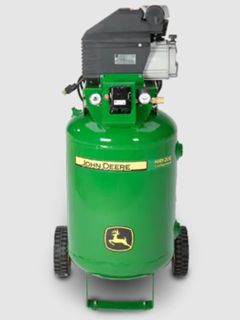
HR1-20E AIR COMPRESSOR
Open up an entirely new toolbox with a powerful John Deere air compressor. Power up everything from air wrenches to drills, grinders and paint guns. You'll find a wide range of horsepower and capacity to suit your needs. And you'll get the satisfaction of a job well done.
DETAILS
20-Gallon, Single-Stage, Electric 2.0 HP, 120V Motor
2.0 HP, 120V Motor 4.1 CFM @ 100 PSI Upright portable design
20-gallon receiver tank
2 semi-pneumatic tires
Protective pump/motor housing
Canister intake filter
Regulator and two gauges
Auto start/stop control set at 95-125 PSI
Drain valves and pressure relief valve
Quick connect fittings
FEATURES
PRESSURE SWITCH
The switch is used to start or stop the air compressor. Moving the switch to the "Auto" (ON) position will allow the pressure switch to start the motor when the air tank pressure is below the factory set "cut-in" pressure. When in the "Auto" position, the pressure switch stops the motor when the air tank pressure reaches the factory set "cut-out" pressure. This switch also has a pressure release valve located on the side of the switch designed to automatically release compressed air from the air compressor pump head and its discharge line when the air compressor reaches "cut-out" pressure or is shut off. This allows the motor to restart freely. Moving the switch to the "OFF' position will open the pressure switch contacts and stop the air compressor.
MOTOR THERMAL OVERLOAD
The electric motor has a manual thermal overload protector. If the motor overheats for any reason, the thermal overload will cut off power to prevent the motor from being damaged. Turn pressure switch lever to the "OFF" position and wait until the motor is cool. Press the thermal overload button to reset it and begin working again.
AIR INTAKE FILTER
This filter is designed to clean air coming into the pump. To ensure the pump continually receives a clean, cool, dry air supply this filter must always be clean and ventilation opening free from obstructions. Replace filter element when necessary.
TANK PRESSURE GAUGE
The tank pressure gauge indicates the air pressure in the air tank.
PRESSURE REGULATOR
The air pressure coming from the air tank is controlled by the regulator knob. Turn the pressure regulation knob clockwise to increase discharge pressure, and counterclockwise to decrease discharge pressure.
OUTLET PRESSURE GAUGE
The outlet pressure gauge indicates the air pressure available at the outlet side of the regulator. This pressure is controlled by the regulator and is always less or equal to the air tank pressure.
AIR TANK DRAIN VALVE
The drain valve is used to remove moisture from the air tank after the air compressor is shut off. NEVER attempt to open the drain valve when more than 10 PSI of air pressure is in the air tank! To open the drain valve, turn the knob counterclockwise. Keep the air compressor in such a position that all water condensation will flow out.
SAFETY RELIEF VALVE
This valve is designed to prevent system failures by relieving pressure from the system when the compressed air reaches a predetermined level. The valve is preset by the manufacturer and must not be modified in any way. To verify the valve is working properly, pull on the ring. Air pressure should escape. When the ring is released, it will reseat.
TANK CHECK VALVE
This valve prevents the compressed air in the tank from re-entering the pump discharge line.
OIL DIPSTICK
The dipstick will indicate the amount of oil in the pump. Oil level should be checked on a daily basis to ensure it does not exceed the maximum notch or fall below the minimum notch on the dipstick.
PUMP OIL DRAIN
The removal of the drain plug will allow the air compressor lubricants to be changed. To remove drain plug, turn counterclockwise.
AIR COMPRESSOR PUMP
To compress air, the piston moves up and down in the cylinder. On the downstroke, air is drawn in through the air intake valve while the exhaust valve remains closed. On the upstroke, the intake valve closes, air is compressed and forced out through the exhaust valve, into the discharge line, through the tank check valve and into the air tank.
Similar models may be shown in addition to the featured model. Equipment may be shown with options.
Specifications are subject to change without prior notice.
Express Financing Get Pre-Approved
Get a FR8Star Shipping Estimate
John Deere Spring Parts Catalog 2024
John Deere Spring Parts Sale Catalog 2023
Make It Better | John Deere LED Rotary Beacon Low Profile RE596223