
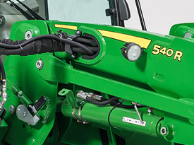
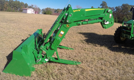
Loader - 540R Back

- Increased lift capacity
- Seat-mounted loader joystick for optimum control, visibility and comfort
- Remote Implement Unlatch
- Automatic mast latch to easily attach/detach loader
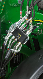
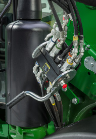 Single-point hydraulic connection on 5R
 Single-point hydraulic connection on 5R
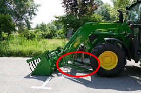
The 540R Loaders comes base equipped with single-point hydraulic connector. This feature saves time and effort when installing and removing the loader.
To disconnect the hydraulic connection between the loader and the tractor, it is necessary to relieve the hydraulic system oil pressure on the tractor.
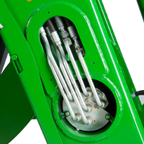
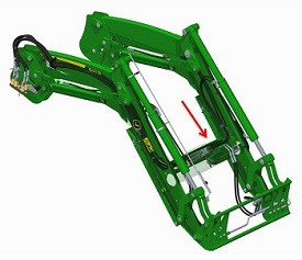
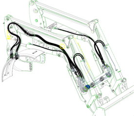 Concealed oil lines through boom arm (picture shown is from H-Series Loader)
 Oil lines routed through the boom arm
 Oil lines routed through the torque tube
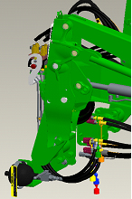
Through time, increased width in tractor hoods have caused issues with available space for running traditional oil lines of a loader along the boom, making them more susceptible to damage.
To improve this situation, the oil lines have been routed through the boom arm and the torque tube, improving line protection and the appearance of the loader.
 Parking stands
 Parking stands
Only leave the operator's station once to disconnect the loader
John Deere loaders are easily removed and reinstalled on tractors without tools. The automatic mast latch (AML) parking system allows removing or attaching the loader to the tractor in minutes without the need for tools.
Easy and quick steps to disconnect the loader:
- Lower the loader to ground, turn tractor off and release hydraulic pressure from joystick
- Exit operator's station
- Open / lower parking stands (both left and right)
- Turn the boom cylinder valve lever to the unlocked position
- Remove loader hydraulics
- Unlock the mast pins (both left and right) and then able to back away
Removing or parking the loader
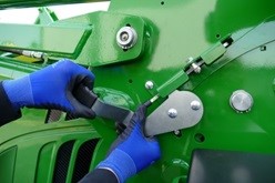
To disconnect the loader, the bucket has to be flat on a stable ground (1). The operator must place the bucket flat on the ground, turn off tractor and release hydraulic pressure from joystick. (2) Exit the operator station and (3) lower the self-adjustable parking stands on both sides of the loader. The self-adjustable parking stands allow the driver to park the loader on irregular terrain and still keep a good position relative to the mounting frame, to attach the loader correctly later on. The parking stands can be set without tools. (4) After lowering the parking stands, the hydraulic couplers on the right-hand side of the loader must be removed and (5) the loader must be unlocked from the tractor mounting frames (both right and left side).
After these easy steps, the operator is ready to move the tractor.
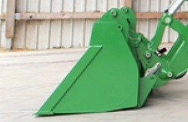 Loader placed on the ground with the bucket leveled (1)
 Open the parking stands (3)
 Remove loader hydraulics (4)
 Loader hydraulics
 Unlock the loader mast (5)
 From operator station, locking pins indicators
Connecting the loader
Connecting the loader is fast and convenient thanks to the ramp design on the mounting frames and the AML equipped with a floating device. Only drive the tractor to bring the mounting frames inside the mast until the latching indicators are in lock position (visible from operator's station). Then the driver can lift up the parking stands, connect the hydraulic coupler for hydraulic and electric loader power to the tractor. Fast, intuitive and maintenance-free design, the loader connection and disconnection brings the tractor ready for any tasks.
 Mounting frame approach into AML
 Two latched indicators from the operator's station
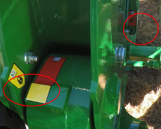
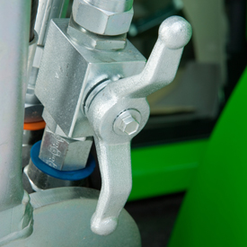 Hydraulic shut-off valve (open position)
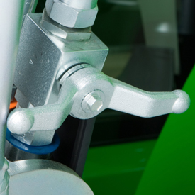 Hydraulic shut-off valve (closed position)
A hydraulic shut-off valve is included with the R-Series Loaders to ensure the loader does not lower suddenly. For example, this allows the boom to be locked out when someone is required to be located under the loader boom for service work on the tractor. It should not be used for extended periods of time unless an appropriate support stand is also utilized.
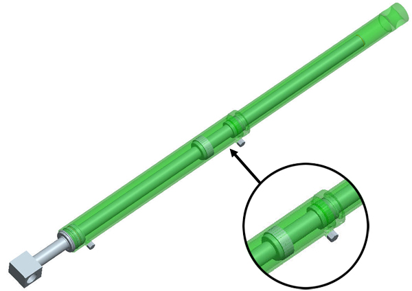 False rod cylinder
Fast bucket cycle times are important to dump the load from the bucket as quickly as possible, (quite often) in order to be as productive as possible, while completing loading operations. The bucket cylinder design can have a major impact on this cycle time, especially for the mechanical self-leveling (MSL) loaders.
All MSL H-Series Loaders utilize false rod bucket cylinders. A false rod cylinder has a smaller displacement of oil requirement on the head end of the cylinder, which allows this cylinder to dump much faster than a normal cylinder.
 LSS
LSS
 LSS on H180
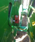
 LSS on 5E and 5M
An enhancement to the loader is the suspension system. A great level of loader productivity is achieved with the LSS.
- An accumulator charged with nitrogen and connected to the head-end lift cylinder hose through a T-fitting provides shock absorption
- The cylinders move in and out to allow the boom to float
Performance
- Bales can be transported more efficiently from one end of the field to the other over frozen, hard-packed, or rutted terrain
NOTE: Check bale handling capability of tractor before use.
- Pallets can be moved easily without sustaining cargo damage
- Pallets of seed or fertilizer can be carried across a yard without a bag spilling and creating a costly mess
- Properly ballasted tractor with LSS has increased stability, creating a smoother ride for the operator
Cost of Ownership
-
Extended life of loader pins and bushings
-
Less stress on tractor axle
Reasons for turning LSS off include:
- Digging applications - with LSS on, the cylinders retract slightly, losing lifting power
- Holding a grade when blading - with LSS on, it is difficult to hold a constant grade
- Precise pallet and bale handling - with LSS on, the load moves up and down slightly while being positioned
- Parking a loader - with LSS on, when down pressure is applied, the lift cylinders retract slightly, making it more difficult to park
The switch is conveniently located in the operator’s station to avoid having to exit the operator station to manually move the handle on the LSS.
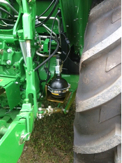
LSS can also be ordered with a manual shutoff. Depending on the tractor/loader model, the accumulator is located in different places. On the H180 the accumulator is mounted outside the bottom of the mounting frame. On the 5 Series Tractors, the accumulator is mounted near the inside of the rear right wheel. On 6 Series Tractors and larger, it is mounted in between the hydraulic connection and the mounting frame.
141.53 in.
1926 kg
4246 lb
2243 kgf
4945 lbf
2609 kgf
5752 lbf
100.94 in.
92.52 in.
18.49 gpm
2828.24 psi
73 in.
619 lb
1926 kg
4246 lb
Measured at 800 mm ahead of pivot (V)
1290 kg
2844 lb
2101 kg
4632 lb
Measured at 800 mm ahead of pivot (X)
1576 kg
3474 lb
2243 kgf
4945 lbf
Measured at 800 mm ahead of pivot (Z)
1567 kgf
3455 lbf
1673 kgf
3688 lbf
At 59-in. (1500-mm) lift height (XX)
2712 kgf
5979 lbf
At ground-level line (ZZ)
2609 kgf
5752 lbf
3595 mm
141.53 in.
At full height - bucket level(B)
3355 mm
132.07 in.
At full height - bucket dumped (C)
2564 mm
100.94 in.
5.47 in.
794 mm
31.26 in.
At ground level - bucket level (F)
2385 mm
93.88 in.
63.75 degree (angle)
Rollback angle, degrees (G)
47 degree (angle)
4.25 seconds
Loader lower, seconds
3.18 seconds
Bucket dump, seconds
3.32 seconds
Bucket rollback, seconds
2.23 seconds